This project started based on my desire to create my own original remote control airplane from drawing, to cutting the parts on a cnc machine that I built from a kit, assembling the parts, and then flying the finished product. There were so many normal type airplanes out there, that I decided that I would do something different. I decided on a saucer shaped plane. The project was such a great challenge from the beginning. First, I had to learn to use a CAD program. I started with a program from Google called SketchUp. It was a painful experience, but it’s a great program to learn CAD drawing on, and, it’s free. After some time, I had a drawing created that included over 50 pieces. The next step was to build the router based cnc machine called a PhlatPrinter. Not as painful as CAD, but still very challenging. The group that created the PhlatPrinter also included the script that would create the gcode file that the cnc machine need to actually cut the parts.
Specs:24″ diameter disc
AUW = about 16oz
A $20 dollar motor/ESC combo (B2212/13 and 18 amp ESC) from RCHotDeals.com is a perfect match for this plane. About 110 watts is what you’re looking for. I prefer at least a 1:1 thrust to weight ratio.
APC 8×4.3 (or smaller) prop
1320 to 1800 mah 3 cell lipo
2 servos (about 15 oz torque) in elevon configuration (like TowerPro 9 gram servos)
3 mm carbon fiber tube/rodsBuild difficulty:
Construction is normal.
Covering foam with heat shrink film will make you sweat. But, the end result is worth it.
Step 1The Cad File
As I noted, the plane was designed in SketchUp. Here are the two files that contain all the plane parts. Being a router based cnc machine, it’s necessary to tell the machine which direction the router should move depending on whether it’s an inside or outside cut. The orange lines are outside cuts, the blue lines are inside cuts, and the pink are partial depth cuts.The SketchUp file (along with hundreds of other planes) is available on the PhlatBoyz site. (
http://www.phlatforum.com/index.php )
Step 2The Parts
Here are the parts that were cut by the PhlatPrinter. The prefered foam type is white 6mm thick depron. Some pictures show parts cut from a cheap blue prototype foam I use called fan fold. It’s the stuff to use while working out how the pieces fit together.
Step 3Assembing the disc part of the airframe
Here are the pieces cut on the PhlatPrinter starting to come together. The project requires 2 sheets of 6 mm depron. I use the 27×39 inch sheets. This length requires that you tape on an additional 8 inch piece across the back end to increase the length in order for all pieces to get cut out properly. You can use blue FF, but, it is not as strong as depron and the parts fit is loose. The cut file assumes 6mm depron for the slots. When you cut your parts, you’ll notice some parts really make the PhlatPrinter’s stepper motors sing.I use foam safe CA on all foam pieces and epoxy on the wood pieces. Glue on spars 1, 2 and 4 to the bottom of the disc in the groves provided. Do not install the center spar yet. It goes on after the ribs are installed. Make sure the disc is flat during this step. Let dry. NOTE: This picture shows the bottom of the disc with most pieces installed. The black tubes are carbon fiber rods to provide frame rigidity.Install Ribs R1, R2, R3, R4, R5, R6, and R7. R3 thru R7 have top and bottom pieces. The small part of R3 thru 6 goes on the bottom of the disc. NOTE: R3 has length wise slots cut into them. This is for the Sullivan cable tubes. Make sure the slots face the center of the disc. The ribs are tabbed for alignment. Use some type of squaring tool during installation. There is another rib (R1a) that goes between R1 and R2. It’s not shown in the layout picture below. It is not installed yet because the servos are mounted in this location. I also use small support pieces on the wingtips to help keep the tips from warping when covering. Although the 6mm depron is probably stiff enough without these pieces. Here is the general layout.
Note also that I use some wooden jig pieces to help keep the frame flat.
Step 4The fuselage
Assemble the fuselage next. Bend the bottom and sides at fold lines to make curved shape. These pieces notch together. Keep square while gluing. Before gluing the 4 nose pieces on, it helps to square up the sides and bottom of the fuse front. After the glue has dried very well, sand the fuselage to shape. The fuse top uses 5 curved pieces to form the canopy. They also help shape the hatch to fit the fuse. Position these so the taller potion of the canopy is toward the back. Notice the piece of ply or bass wood at the front of the battery compartment. A 1/8” dowel is glued to the hatch that is inserted into a hole made in this piece. The hatch also uses a magnet to hold down the aft end. The top/hatch has a spot for a magnet to be glued. Also, there is a ¾” x 2 ½” piece that has a recess cut into it that installs on the disc just under the hatch magnet location. I like to use a 3mm panel to separate the battery from the rest of the equipment. You can see an example in the picture below.
Step 5Hinging the elevons to the airframe
This plane uses control surfaces called elevons to contor pitch and roll. Now is a good time to cut the hinge slots in the disc and elevons. I prefer to use 3 Du-Bro nylon pinned hinges (#117) on each elevon. Use the hinge method of your choice. The picture shows 2 hinges on each side.
Step 6Install the T shaped doubler
Install the T shaped frame doubler to bottom of disc. The top of the T lines up with the center section trailing edge. You can bevel the leading edges of the outside part of the T if desired.
Step 7Install the main spar
Temporarily install fins to position center spar. This is to help line up the center spar before gluing the spar. Do not glue the fins.There are 8 square pieces of foam with holes in the middle that are used to help secure the spar to the ribs. They go on the inside of ribs R3-R6. Install center spar by inserting the spar thru the holes in the ribs and thru the square support pieces. Make sure the ribs are straight while gluing the squares to the spars. Remove the fins for now.After glue has dried, it’s time to sand the leading edges of the ribs to meet the disc. Carefully shape the top and bottom leading edges of the ribs. I prefer to sand the edges to make about a 1/8” thick leading edge. Also, if you use the wing tips braces, they need to be sanded also.
Step 8Control surface reinforcement
Now make 2 elevon control horn panels out of 1/32” basswood. I prefer extra support for the elevons so I make these pieces 2 1/4″ x 3”. Glue these to the bottom of the elevons as shown.
Step 9Motor mount
Make the motor mount out of 1/8” plywood. Size is 2 ½” x 4”. I use a stick type motor mount. I prefer to use two 2-56 screws with T-nuts installed on the bottom of the mount. You will need to determine the screw holes location for your particular motor mount. The picture shows the 1” x 3/8” slot along the left front edge of the plywood for the motor wires.
Step 10Install servos
12. It’s time to install the servos. Use rib R1a to help locate the install point. I prefer to cut out a hole for the servo to set into and make it flush with the bottom of the disc. This is a good idea also because the control arms are barely long enough to extend thru the foam. Note the receiver antenna going thru the ribs of the right side.
Step 11Next steps
13. Temporarily install the elevons. Install the Sullivan cable to the servos. Run the plastic cable tube down the slots cut into R3. Glue the tube to the slot. Line up the control horns and attach horns to the bottom of the elevons on the basswood. Finish the cable hook up to the elevons using Du-Bro easy connectors. Now test the elevons. When satisfied everything works well, disconnect the cables and remove the elevons. It’s better to leave off the elevons until the disc covering is complete.14. Now install ribs R1a over the servos. This rib is used to help with the covering process. The gap is too wide between R1 and R2 for the covering to install well.
15. Test install the fuselage. It may be somewhat tight, but it should slide in fairly well. If all looks good, then glue on fuselage.
16. Now is a good time to cover the fins, elevons, and fuselage. However, it is not necessary to do this. I prefer to cover these pieces to enhance the looks and for protection. It’s a good idea to at least cover the fuselage bottom to protect it on landings. If covering the fins be sure to leave foam are exposed that will be glued to the ribs.
17. I prefer to install the receiver before covering the wing. I like to run the antenna around the right side of the disc. This is just a preference. See # 12 above.
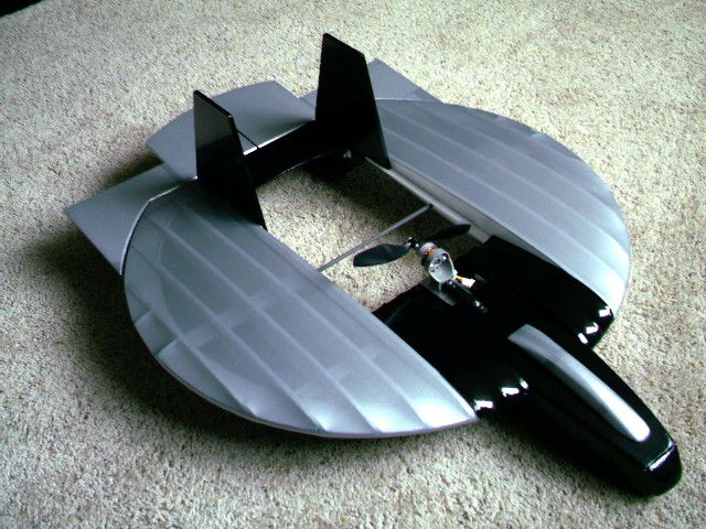
18. Here’s what your saucer should look like prior to covering.
Step 12Ready to cover the frame
19. Now cover the disc. This can be a challenge with the curved wing design. I get the best results by covering ribs R3, R4, and R5 with one piece. Then cover R5 thru R7. Always start on the bottom first. It’s best by far to use a very lite covering film like Coverite MicroLite from Tower Hobbies. It weighs .6 oz per sq yard. Don’t use Sig ultra light. It does not stretch and shrink very well for covering foam. Take your time with the covering process. It does pay to experiment. Iron temp should be about 220 degrees. After covering, be sure to check for wing warps. If you have some, you can use heat to straighten it back out.20. Glue the fins to ribs R3. Make sure they are pressed against the ribs and square to the disc before gluing.
21. Glue the hinges to the elevons and install/glue to the disc. Or do your preferred hinge method.
22. Attach cables to control horns. I like lots of throw on both aileron and elevator. If you can’t set exponential with your radio, you may want to reduce throws some.23. Install motor, esc, and receiver. You will need to cut a slot for the motor/esc wires. It seems to like the aft part of the motor angled slightly up. The plastic stick mount I use naturally gives about 1/32” up thrust.
Step 13Final steps
24. Test all functions.
25. Start out with the CG just in front of the second spar. It is not very CG sensitive. So adjust to your flying preferences.
26. Check lateral balance. You will probably end up with several clicks of right aileron to offset the motor/prop torque. This can also be controlled by adding about 3 grams of weight to the right wing tip.
27. I like to give a few clicks of up elevator to start with. And then trim in flight.
28. I use about 60% exponential to smooth out the normal control.
29. A mild toss with about ¾ throttle will get it on its way. Watch out for your fingers!
30. When landing, be sure to release the elevator. The outer part of the elevon will dig into the grass.
31. Now, have some fun!Short video included. It was quite windy for this flight. But, for a 16oz plane, it does very well.